Domestic Electric Test Checklist

Talk Electrician Forum

Help Support Talk Electrician Forum:

This site may earn a commission from merchant affiliate links, including eBay, Amazon, and others.

SirLouen

Active member
Joined
Nov 10, 2022
Messages
33
Reaction score
0
Location
Europe
If you had to test a whole installation that someone else have done, do you have a checklist of elements you shall be doing to see if everything is in the right place?

I'm like to write it down. Some elements I've been thinking on, I would like if you could write 1 or 2 I've missed, I will be updating the list to have a good and comprehensive list with all the best items that should be tested.
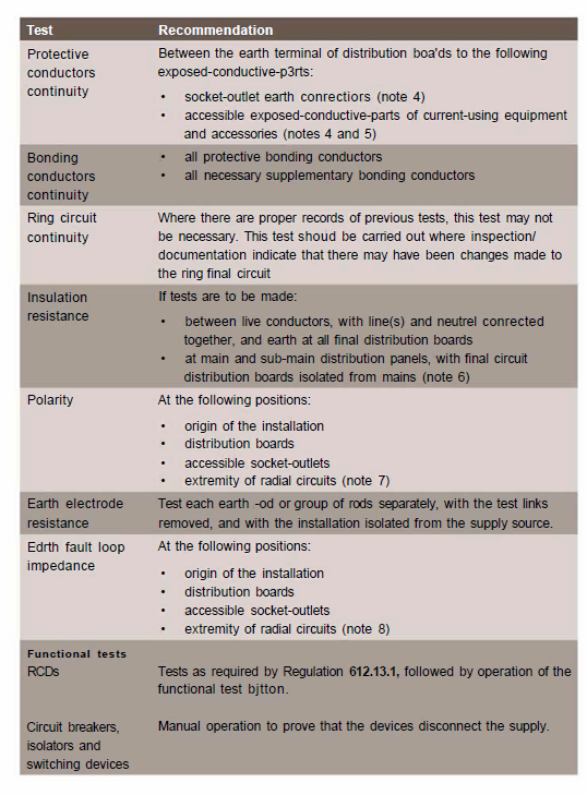
  1. Continuity of protective and ponding conductors
  2. Continuity of ring final circuit
  3. Insulation resistance with a meg tester
  4. Polarity testing
  5. Earth electrode resistance
  6. Earth fault loop impedance
  7. RCD disconnection timing
  8. Phase rotation/sequence test
  9. Functional testing
  10. Voltage drop
  11. Thermal analysis with thermal camera
  12. Harmonic distortion with network tester

I just want to have a checklist for personal uses. If you think any other interesting or important test should be done, please comment.
 
Last edited:
Most of the elements in the list I've written come from there.
But I'm willing to hear new ideas
 
are you thinking of new installations or existing installations?
For example, a friend, family, or some type of relative, calls me to do some thorough domestic testing.
Not for something I have installed, but something that someone unknown has already installed.
 
so EICRs ….
Yes, I know that EICR are basically one of many things I'm looking for. But I'm just trying to compile a further checklist.
I'm not looking where to find checks because, as you may see, I've already compiled most of the top classic checks in the list.

For example, in the periodic checklist EICR manual suggest, that are basically all the test I've already mentioned above.

IqVo31S.png


I'm looking for more tests. Not the official and regulatory tests, in other words, not the tests that are in the classic books.

For example, as I mentioned, things related with harmonic distortion is something interesting to include. New ideas, like that, are the kind of tests I would like to introduce under my list, and this kind of ideas that could come from experience are what I would like to share.
 
There are no more tests required.

If your carrying out just inspection and testing of someone else's work then you issue an EIC but you only complete the inspection and testing boxes.

The designer and installer fill in the others.

You then carry out the tests in the order specified in BS7671. As you are building up layers of safety before energising the circuits.

As the inspector that's all your there to do. Voltdrop and the other things mentioned are the responsibility of the designer and installer.

If there is no designer and installer ( you have inherited the job as the previous person left or was sacked ) then you can only issue an EICR. However I would still carry out inspection and testing as if I were doing an EIC ie all tests on all circuits.

Again no need for any further tests. Experience is going to tell you if your potentially going to have issues with voltage drop, then it's down to you to explain the non compliance to the client.

It's your name on either certificate and if your signing to say an installation is safe and its not, your the one who's going to be stood in front of the person in robes and a funny wig justifying your actions.
 
only real thing to add to EICR's would be thermal imaging, but not many people have thermal cameras to do that anyway

And the MKI eyeball - finds more faults than everything else put together.... well as long as you know where to apply it... normally anywhere that appears to have had an invasion of DIYers/ kitchen fitters / shop fitters / the guy who drives the forktruck but also 'fixes' stuff around the site
 
I'm looking for more tests. Not the official and regulatory tests, in other words, not the tests that are in the classic books.
For what purpose, are you trying to find a fault before it occurs
only real thing to add to EICR's would be thermal imaging, but not many people have thermal cameras to do that anyway
And most of the time there is very little to see or note

It is all very well doing all the tests and whatever extra tests you think that may be of some limited use but the bottom line is that if you don't understand what the numbers or pictures are telling you then they are all pretty pointless
 
You need to bear in mind that it’s Inspection AND test. The visual part of doing EICRs is more important than a lot of the tests.

for starters, identifying what each circuit actually does can take some time, as does inspecting a sample of the connections and looking at all the accessories
 
For what purpose, are you trying to find a fault before it occurs
For example, on a brand new installation, suddenly you see that there are like 5V on an earth-neuter contact. When there should be at most 1-2V. Why so? This is part of a regular test for continuity.

But then I find that there are like 10mA due to harmonics in the circuit. I know that as soon as it reaches 15mA the RCD is going to trip. Why there are like 10mA if there should be at most 1-2mA on the network? It would be nice to find the source of the issue.

Maybe I see this like a regular blood analysis: you might have all parameters in order, but suddenly, you see that cholesterol levels are slightly high, so better warn than curing?

Probably this is too much of a hassle for most.

only real thing to add to EICR's would be thermal imaging, but not many people have thermal cameras to do that anyway
Interesting this one. I saw some docs regarding this topic but have not gone deeper. Have you experienced with this?

Recently, they set a 6mm2 for the grid-panel connection on a friend's house, with 9kW and the technician told them that it was not worth to put the 10mm2 even though under the rulings it says that for 40A+ there should be 10mm2 at least (funny that he signed the certification with a 10mm2 cable)

I wondered the heat that those cables are picking when they went above 7kW

the guy who drives the forktruck but also 'fixes' stuff around the site
Trust me, there are certified technicians worse than that guy. Electricity rules are always progressing, and many guys with 20-30 years in the business, are now completely obsolete or think that the rules are a whim, so they keep building things the same way they did 30 years ago, and many sign certifications without caring about the reality of what they installed (as I mentioned in the previous paragraph)

Yesterday I was discussing with this man, that the SPD was mandatory nowadays, at least highly recommended since first in 2004 draft and officially mandatory after 2013 (at least in my country), and the guy replying me that lightnings only ocurr in certain parts of the USA and neuter issues in the grid are almost impossible, so setting such SPD was a waste of time and money (another certified technician)

I'm also setting my checklist because I want to give it to the technicians to check and sign. Here in my country at least this is not mandatory to be done explicitly. This is something that is implicitly known to be done, but the reality is that this is rarely done (at least not as thoroughly as I would like). Maybe I'm too picky, but personally, I would conduct a test of every single socket to check if there is right continuity. Some don't even check if the plug is working... imagine checking continuity.

Also, many technicians work with unattended apprentices, and they sign despite the work of them. This is very intricate and I have difficulties trusting by default.

Again no need for any further tests. Experience is going to tell you if your potentially going to have issues with voltage drop, then it's down to you to explain the non compliance to the client.

As I said, I'm not concerned about signatures and certificates. This is something personal.
 
What test meter are you using to show 10ma due to harmonics? Or are you referring to Earth Leakage? If there is noise or voltage in continuity testing your test meter should alert you and decline further testing.
 
What test meter are you using to show 10ma due to harmonics? Or are you referring to Earth Leakage? If there is noise or voltage in continuity testing your test meter should alert you and decline further testing.

HT GSC60

Yes, 10mA are the earth leakage, with the network analyzer then you clearly see the wave lenght and the presence of harmonics. From there one could detect which electronic device is provoking such, and replace it or put a class A RSD

But for me, the interesting thing is not only to find the leakage but the cause, even if is not as high as 10mA
 
Last edited:
Interesting this one. I saw some docs regarding this topic but have not gone deeper. Have you experienced with this?

yes, i use thermal camera for EICR's. usuall its jsut a look over connections at the DB, sometimes at isolators. found a few connections hotter than the others a few times and faults can be fixed before they burn out. depends what the customer wants though
 
yes, i use thermal camera for EICR's. usuall its jsut a look over connections at the DB, sometimes at isolators. found a few connections hotter than the others a few times and faults can be fixed before they burn out. depends what the customer wants though
Which camera do you have?

@bglproserve I picked it from Amazon for £3500
 
Top