How to test current transformers

Talk Electrician Forum

Help Support Talk Electrician Forum:

This site may earn a commission from merchant affiliate links, including eBay, Amazon, and others.
Joined
Mar 9, 2008
Messages
2,022
Reaction score
56
Location
Doncaster
As per title really,

How does one test an in-situe split core current transformer?

As part of the latest PV job we have been labouring on, it had to have export limitation. The incomer had 3 cores / phase and some there was 3 CT's per phase and each bunch of 3 then ran through a current summation transformer. I never done this sort of thing and we were against the clock. The shut down was 2 hours late due to other influences, not us. We fitted them all and connected the to the cable that I had previously ran from the export limit panel. when we powered back up only 1 phase was reading. so we had to order for the tx to be shut off again, luckily no other plant was turned on.

Out of 3 of us, none knew how to test the CT's so all we could do was recheck our work. I did find a lose factory connection so thought that would fix one of the phase sets, but it didn't. Anyways, we were ordered to turn back on and leave at 7pm last night so had to leave it as was.

How could we have tested them to figure out better what was going on and with current summation transformers is it a case of if one of the CT's in a phase set wasn't working then there would be no reading? I doubt there would be 6 not working at all?

Cheers

 
orientation of the CTs maybe the culprit?
Nah, all were fitted the same way and one set was reading correctly.  

Found out what it was today. Some links in the export limit panel that nowhere did it say to remove them. No physical labels and nothing on paperwork. 

All sorted now. Think I will keep trying to know how to test them though, just in case for future. 

Cheers

 
Conventional CT's are V/A.

You must never open circuit the output of a CT as the output voltage can rise to astronomical levels, potentially fatal even.

 Find out what the rating is, e.g  100mV/1000A, the CT impedance and the required load impedance etc.

Then ensure that they are connected to the load, and that the load is correctly dimensioned for the CT output.

i.e. correct voltage range & input impedance to match the CT output.

Measure the output voltage with an accurate mV meter, measure the current flowing with an accurate clamp meter, do the maths and you will see if they are correct.

The polarity will give you an idea of the sense.

The links were almost certainly  shorting links to ensure that the CT's when connected were never allowed to open circuit.

Nice to see the kit that you have to work with complies with statute law, NOT!

Another imaginary CE mark obviously.


Well, the CT's were provided with the limiter. Ratio was 1000A / 5A and the CT's had shorting links in them which I removed once the leads were connected and just before coupling them around the conductors (split core CT's).

All work was done with the LV Tx turned off too.

So with the limiter switched on, are we saying I would have a voltage to confirm that 'something' is happening??

Assuming something in the region of the reference voltage +/- something.

 
As Binky pointed out reverse orientation is the likely culprit.

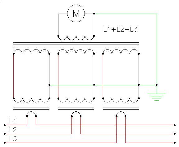
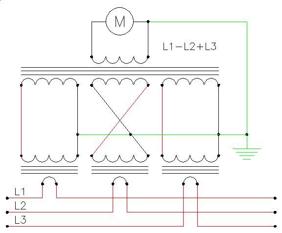
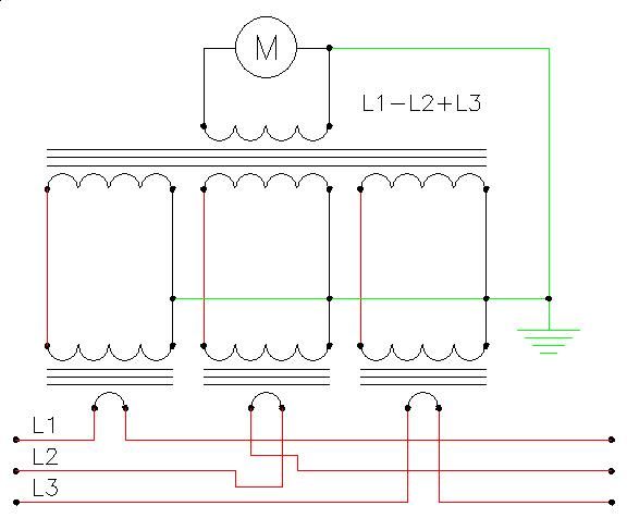
There is a way to test orientation but it would need the metering system to be off line.

CT-sumation-01_zpskq7hrqag.jpg


CT-sumation-02_zpsmkkp8sua.jpg


CT-sumation-03_zps172az9i0.jpg


BTW

Thanks for logging my mind, summation is something I’ve got to add to something I’m writing

 
Well, the CT's were provided with the limiter. Ratio was 1000A / 5A and the CT's had shorting links in them which I removed once the leads were connected and just before coupling them around the conductors (split core CT's).

All work was done with the LV Tx turned off too.

So with the limiter switched on, are we saying I would have a voltage to confirm that 'something' is happening??

Assuming something in the region of the reference voltage +/- something.
OK, so they are true CT's thus they are A/A.

In which case they are really able to generate serious voltages!

In which case there may well have been further shorting links within the control panel.

To be compliant with statute law, these must have been indicated to you in the commissioning documentation.

If they are A/A CT's then you need 2 off current clamps.

One to measure the primary current and the second to measure the secondary, they should be in the ratio of the CT's in your case the secondary would be 0.5% of the primary current.

e.g. for 100A primary 0.5A secondary, this would then indicate that they were at least picking up the primary current.

Following this you would, as has been suggested elsewhere, need to check the "sense" of the secondary current, to ensure that the CT's were correctly connected.

Also, some, only some, CT's require a power supply to operate, so, that needs also to be present and correct.

 
Canoeboy said:
@Barx - photos of this solar export limitation panel please ?
hmmmm, actually, was probably the only thing I didn't take a photo of the inside of. oops

This is the unit before I mounted / connected it.

The CT's connect to this, then this controls another panel which is basically a contactor board (which I do have photos of if need)

20160324_151158.jpg

 
Canoeboy said:
Id like to see the inside


Wish I could help you there, but I don't think I will be going back now as all is up and running.

The bottom section is just for connecting. So, on left was a set of Din connectors for 3ph supply. Then on right was 18 x Din connections for CT's.

In top, CT's were connected to Current Summation transformers with the output going to the front panel. There was some other bits in there but I cannot remember, sorry.

The contactor panel was just that. As seen below. This panel could switch 6 x inverters. We also had a very similar (but bigger) panel that was for Fire Alarm control and that cut out all 13 inverters.

I enjoyed wiring them up ;)

20160324_151223.jpg

 
Yep,

Earths do not comply with EN standards, end of.

That is enough.

Other than that.

Colour codes are to BS7671 not harmonised standards thus the panel cannot be CE marked under LVD if it is to 60204-1.

If it is to 61439, then there is a whole other raft of stuff.

 
Yep,

Earths do not comply with EN standards, end of.

That is enough.

Other than that.

Colour codes are to BS7671 not harmonised standards thus the panel cannot be CE marked under LVD if it is to 60204-1.

If it is to 61439, then there is a whole other raft of stuff.


I'm not questioning your judgment Sidey, I just trying to learn. Learn why it isn't compliant.

As I say, It was ordered by the firm who's job it was, we were just asked to get it on the wall. The panels were built by a supposed 'proper' firm who deals with this sort of stuff.

 
OK,

Standards for compliance with statute law require no more than a single "earth" wire per terminal connection.

So, the picture you have shows more than one, thus illegal.

We are not talking about BS7671 here, we are talking about compliance with statute law, and being legal for supply in the UK.

This panel is illegal for sale, supply & use.

End of.
OK, Cheers for the insite.

 
Top